Challenged Lighting

Skills: SolidWorks, 3D Printing, Mechanical Design, Mechanical Testing
A testing fixture used to evaluate a robot camera's ability to identify a tag on a docking station under intense light conditions, with an adjustable one-dimensional movement and axis rotation for both the camera and dock.

Objective

During my time as a System Test Engineering Co-op at iRobot, I went on this independent design challenge aimed at creating a testing fixture. The primary goal was to develop a setup able to mount both a camera and a robot docking station to evaluate the camera's ability to identify a tag at the docking station under extreme lighting conditions. Specifically, the fixture needed to accommodate a one-dimensional movement along a beam for both the camera and the docking station, with the ability to tilt the beam up to 90 degrees relative to the ground. The camera and dock should also be capable of rotating around their axes and locking at precise angles with the whole fixture also needing to lock securely in any position. The overall goal of this project was to create a challenging lighting environments with direct sunlight or by using stadium lighting, and determine the optimal identification distance for the docking station through the motion of the camera. The image on the right is an example of what a docking station with a tag looks like.

Design Process

Frame Design

My design process began with brainstorming and conceptualization. I focused on creating a solution that could be transitioned between indoor and outdoor environments while ensuring durability and ease of assembly. Given the need for frequent relocations and the potential for repeated use across various projects, I selected 40x40 T-slot Aluminum Extrusions as the primary structural material. These extrusions were chosen for their lightweight, durable, and weather-resistant properties, along with their ease of assembly and the availability of compatible connectors and joints.
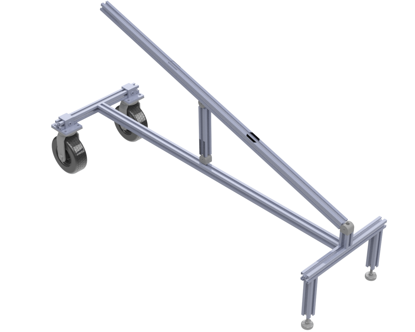
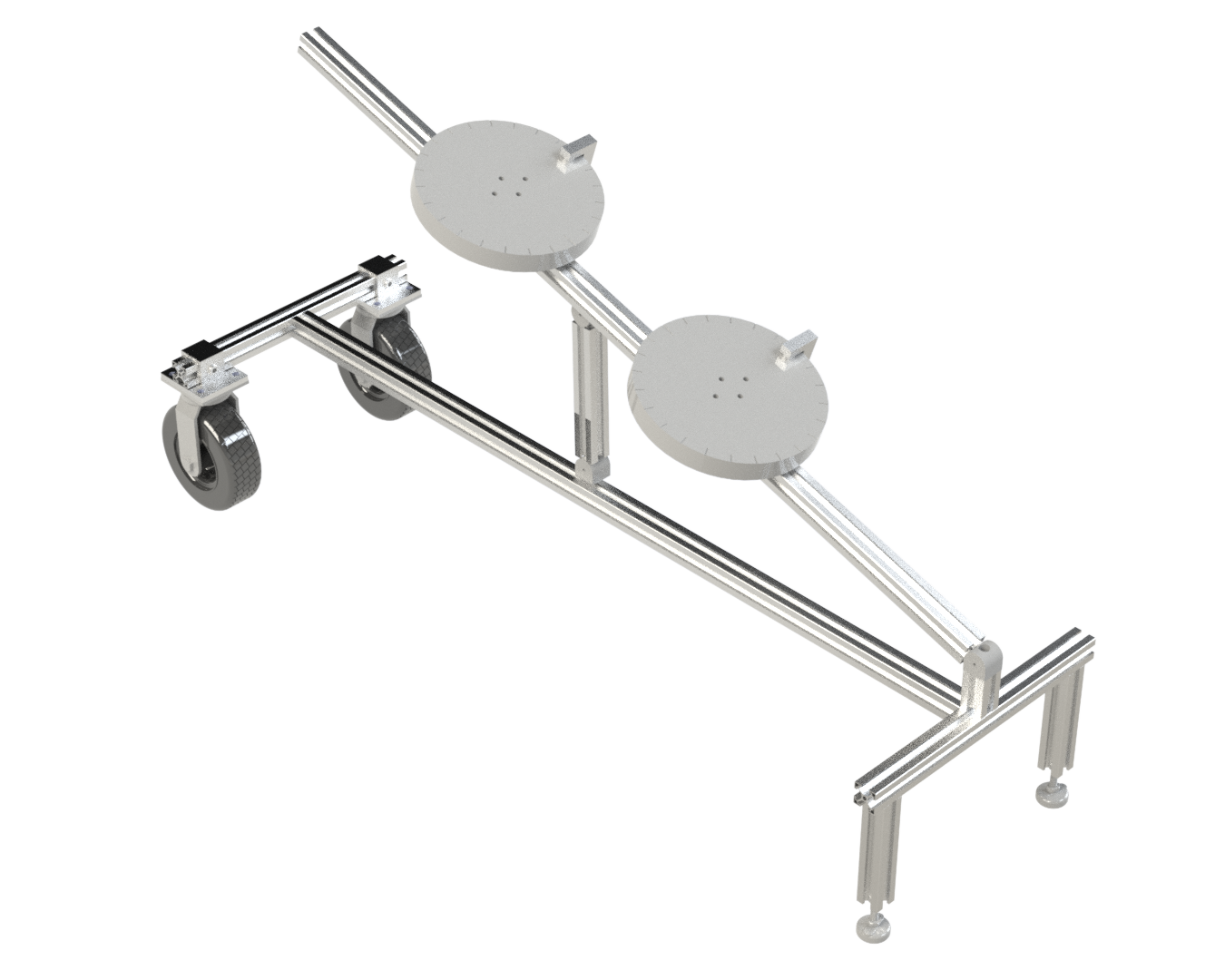
The frame's design features an I-shaped base to maximize stability while minimizing material usage. The centerpiece of the frame measures 1.5 meters in length, with side pieces of 0.5 meters each. To enhance mobility and stability, I used McMaster-Carr solid rubber wheels with an 8-inch diameter. These wheels are extremely robust to support the assembly’s weight, require little to no maintenance, and are well-suited for outdoor use on various terrains, including grass and dirt. To simplify operation, all wheels were clustered on one side of the frame, allowing the operator to easily lift the opposite end and maneuver the assembly. For additional support, I used two Robotunits adjustable beams and stands instead of extra wheels, enabling the fixture to be perfectly leveled in different environments. The image on the right shows a 3D model of the frame with the wheels and the stands.
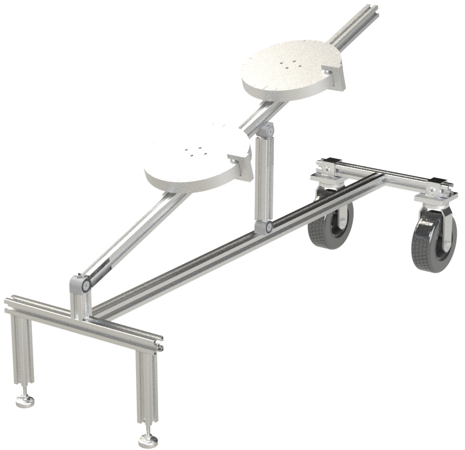
The most complex part of the design was developing a structure capable of adjusting the angles of both the robot and the docking station relative to the ground. After looking back at a couple early sketches, I opted for a simple triangular design. This design includes a 1.5-meter beam attached to a Robotunits hinge at the end of the assembly, serving as a track for the dock and robot to move freely along its length. A 0.25-meter beam, equipped with hinges on both ends, was incorporated between the base and the track to facilitate changes in the angle with respect to the ground. This allows the users to adjust its position before locking the assembly securely in place. The image on the right shows a 3D model of the frame with thetriangular design.  

Sliders and Platforms

With the frame complete, the next challenge was to create a mechanism to attach the camera, robot, and dock to the track while allowing linear movement. To address this, I designed a diamond-shaped slider capable of securely attaching to the track and moving along it. The slider feature heat inserts where we place both M6 screw for locking the slider in place, and four additional M8 screws on top for mounting the platform. The sliders are all 3D printed using PLA filament, and the heat inserts are made of Brass. The images below show the slider's 3D model and final printed part side by side.
Another custom 3D-printed slider was designed specifically to attach the solid rubber wheels to the fixture. Like the other sliders, this one is made from PLA material and it also has four brass heat inserts, allowing M8 screws to be securely fastened through it. The image on the right shows a 3D model of the part.
The platform serves as the base for the camera, robot, and docking station, allowing for rotation around its axis. Rotation was a critical requirement for the lighting test, and the platform was designed to rotate in 5-degree increments and lock at specific angles. The final platform design was waterjet-cut from 0.5-inch thick aluminum plates, chosen for their durability and resistance to oxidation. The platform’s top plate is removable and can be securely locked in place using a simple clamp, allowing the user to precisely adjust the angle of the camera, robot, or dock without constantly measuring deviations. The bottom of the platform is attached to the slider with M8 screws, providing a sturdy connection. The images below show the final water jet cut platform pieces.

Final Assembly and Future Improvements

Due to a Non-Disclosure Agreement (NDA), I am unable to show the fixture in use with the dock, camera, and robot mounted. However, I can confirm that the fixture performed exceptionally well during testing. My supervisor is now responsible for making any necessary improvements and producing at least five more of these assemblies to facilitate testing multiple robots and cameras simultaneously. One potential improvement for future iterations is simplifying the process of loosening and tightening screws, which would overall enhance operational efficiency and ease of use for the operator. The image below shows both the final SolidWorks assembly and the final physical assembly.